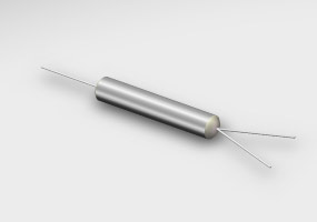
Two couplers can have the same nominal splitting ratio and still produce very different results in an optical system. The difference often becomes visible when engineers examine insertion loss and return loss rather than looking only at the coupling ratio. For mini PM couplers used in precision optical systems, these parameters help determine how efficiently optical power is transferred and how much unwanted reflected light can travel back toward the source.
This distinction matters because a coupler is part of a larger optical budget. Every fraction of a decibel lost in a passive component reduces the power available to downstream devices. At the same time, unwanted reflections can interfere with sources and other sensitive optical components.
Insertion loss describes the reduction in optical power associated with introducing a component into the optical path. In practical terms, engineers use it to understand how much signal power is lost as light passes through the coupler.
For a system containing several passive components, these losses accumulate. A coupler with modest insertion loss may be acceptable in one architecture but become a significant concern when combined with multiple splitters, connectors, switches, and long fiber paths.
When comparing a PM fiber coupler, engineers should therefore look beyond the nominal splitting ratio and examine the complete loss specification.
Return loss addresses reflected optical power rather than transmitted optical power. A higher return loss generally indicates less reflected power returning toward the optical source.
This can be important for systems using sensitive laser sources or architectures where reflections may affect signal stability. If reflected light travels back through the optical path, it can create effects that are unrelated to the intended coupling function.
That is why insertion loss and return loss should not be treated as interchangeable specifications. One primarily describes transmitted power loss, while the other describes the suppression of reflected power.
| Parameter | What it evaluates | Typical design concern |
|---|---|---|
| Insertion loss | Optical power lost through the component | Available power and system optical budget |
| Return loss | Reflected optical power | Source stability and reflection sensitivity |
| Splitting ratio | Distribution of optical power between ports | Power balance between optical paths |
| Polarization performance | Preservation of polarization behavior | Stability in polarization-sensitive systems |
A coupler designed for a balanced split does not have the same power distribution requirements as one designed for an asymmetric split. For example, a 50:50 architecture divides optical power more evenly, while an asymmetric configuration intentionally directs most of the optical power toward one path.
This means that insertion loss should always be interpreted together with the intended coupling ratio. Looking at a single loss number without understanding how power is supposed to be distributed can lead to an incomplete evaluation.
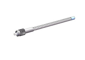
For engineers comparing different PM fiber assemblies, the same principle applies at the assembly level. The performance of the individual coupler is important, but connector interfaces, fiber alignment, splices, and other optical interfaces can also contribute to the total system loss.
.jpg "PM fiber assemblies")
Mini PM couplers are often selected for applications where polarization behavior cannot be treated as a secondary concern. A polarization-maintaining architecture is designed to reduce unwanted changes in the polarization state as light travels through the optical path.
The fiber itself is therefore part of the performance equation. A polarization maintaining fiber must be properly aligned and integrated if the system is expected to preserve the intended polarization behavior.
This is one reason why evaluating a coupler in isolation can be misleading. Even if the component meets its nominal optical specifications, poor alignment or incompatible downstream components can affect the performance of the complete assembly.
There is no universal answer. The priority depends on the optical architecture.
If the system has a limited power budget, insertion loss may become the dominant consideration. If the system uses a reflection-sensitive laser or precision optical measurement architecture, return loss may receive greater attention.
In many cases, both should be treated as minimum requirements rather than competing targets. Establishing acceptable ranges for each parameter before evaluating suppliers makes the selection process more objective.
A practical comparison should start with a specification matrix. Instead of comparing only one headline parameter, record the values that affect the actual application.
Operating wavelength
Coupling ratio
Insertion loss
Return loss
Polarization extinction ratio or equivalent polarization specification
Fiber type
Package dimensions
Operating temperature
Long-term environmental requirements
This approach makes it easier to identify trade-offs. A component with slightly better insertion loss may not be the better choice if its package is difficult to integrate or its polarization performance does not satisfy the system requirements.
Optical designers should calculate the complete link budget rather than assuming the performance of one component determines the system result.
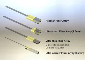
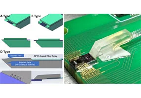
Consider a compact optical module containing a coupler, fiber array, connectors, switch, and detector interface. Each interface contributes to the final optical budget. If several components are selected independently without considering their combined losses, the completed module may provide less available optical power than expected.
This is particularly important during prototype-to-production transitions. A laboratory setup may use carefully controlled connections, while a production assembly introduces additional tolerances and interfaces. Component specifications should therefore leave sufficient engineering margin.
Return loss becomes particularly relevant when reflected light can influence the optical source or measurement path. In a sensitive system, even a small amount of reflected power may become significant when it interacts with other optical components.
For this reason, return loss should be considered early in the architecture rather than checked only after the optical module has been assembled. Doing so gives engineers more flexibility to manage reflections through component selection, fiber routing, connector design, and optical isolation.
The most reliable selection process treats insertion loss and return loss as part of a larger set of requirements. Splitting ratio determines how optical power is distributed, insertion loss determines how much useful power is lost, return loss indicates how much power is reflected, and polarization performance determines whether the optical state remains suitable for the application.
For compact PM systems, these factors should be evaluated together with packaging and assembly requirements. A technically strong coupler is not necessarily the right choice if it cannot be integrated efficiently or if its performance leaves insufficient margin for the rest of the optical path.
Ultimately, the right mini PM coupler is the one whose optical and mechanical characteristics fit the complete system—not simply the one with the most attractive individual specification.
 English
 日本語
日本語 한국어
한국어 français
 Deutsch
 Español
 italiano
 русский
 português
 العربية